Create symbol and hierarchical schematic in Xschem


Ming Sun / November 05, 2022
5 min read • ––– views
In this blog post, let us create a simple nand2 logic gate in Xschem. And then we are going to use Skywater130 PDK and Ngspice to simulate it.
Step 1 - Create the nand2 schematic
If you are not familiar with
Xschem, please follows Ref. [1~2] to learn how to import devices and run simulations inXschem.
Create the nand2 schematic as shown in Fig. 1.

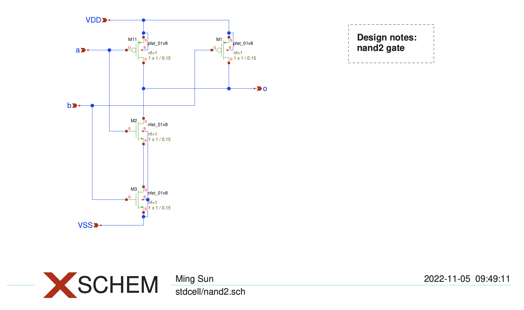
The symbols used in the schematic are listed below.
| Cells | Library | Descriptions |
|---|---|---|
| pfet_01v8.sym | sky130A/libs.tech/xschem/sky130_fd_pr | 1.8V PMOS |
| nfet_01v8.sym | sky130A/libs.tech/xschem/sky130_fd_pr | 1.8V NMOS |
| title.sym | xschem/xschem_library/devices | title block |
| ipin.sym | xschem/xschem_library/devices | input port |
| opin.sym | xschem/xschem_library/devices | output port |
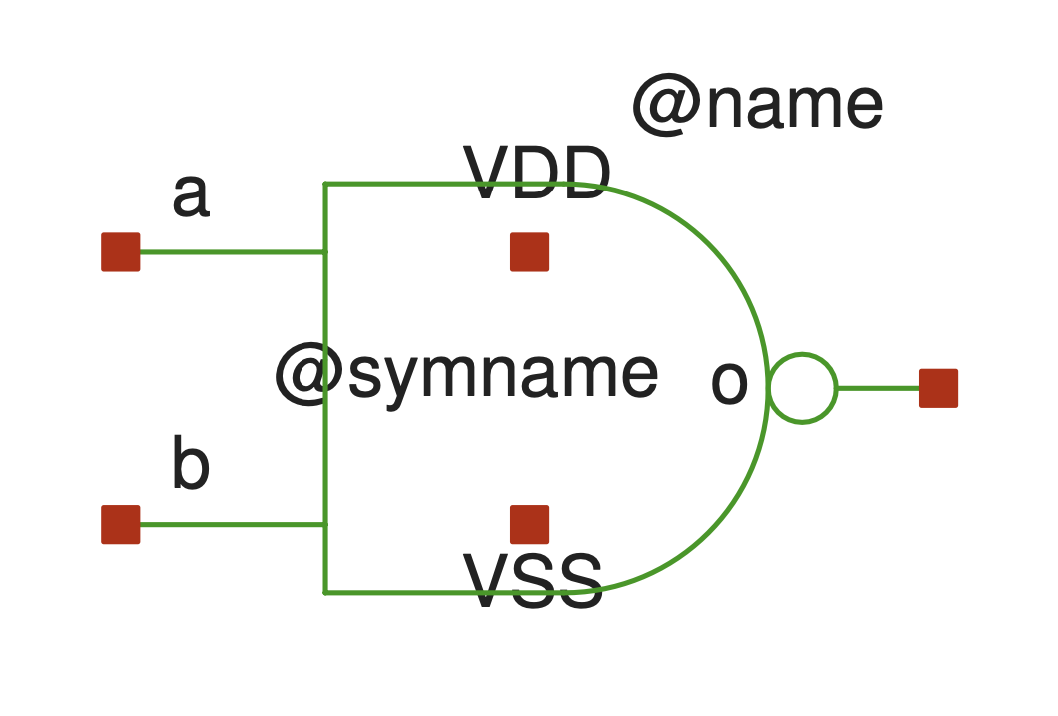
Step 2 - Create the nand2 symbol
At nand2 schematic, press bindkey a to create symbol as shown in Fig. 2.

For the shape, such as line, arc, circle, you can use the following bindkey to create[3].
| Bindkey | Descriptions |
|---|---|
l | draw line |
shift-c | draw arc |
control-shift-c | draw circle |
Another way to draw the symbol is that we can open the nand2_1.sym symbol under this path /usr/share/pdk/sky130A/libs.tech/xschem/sky130_stdcells.
Step 3 - Create the test bench
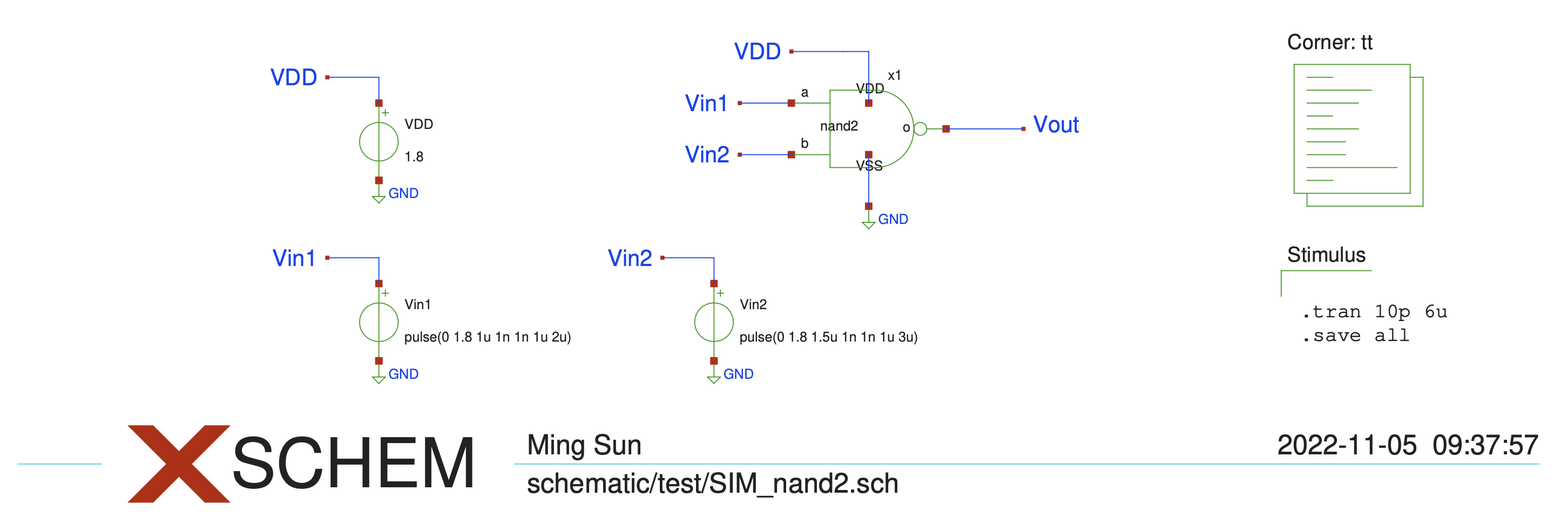
Next, we can create the SIM_nand2.sch test bench to simulate the nand2 standard cell we just created. The test bench is as shown in Fig. 3.

The transient simulation result is as shown in Fig. 4.

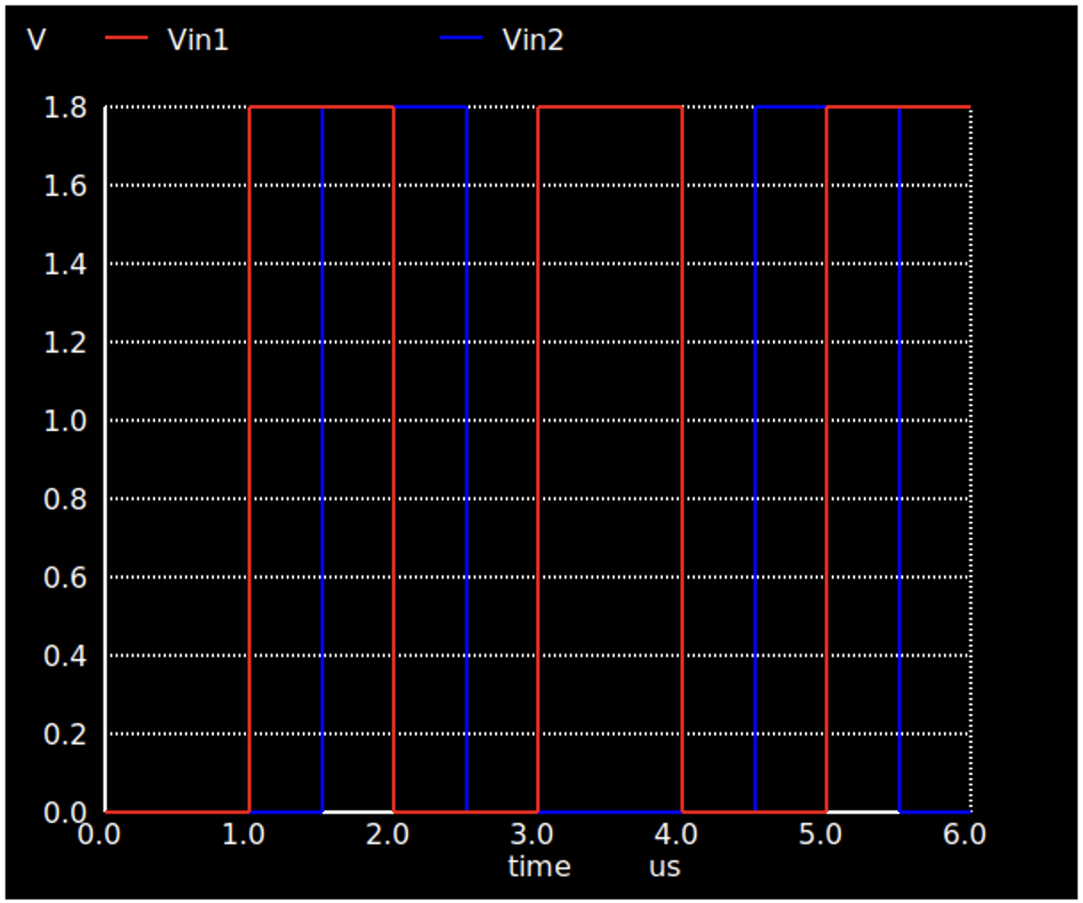
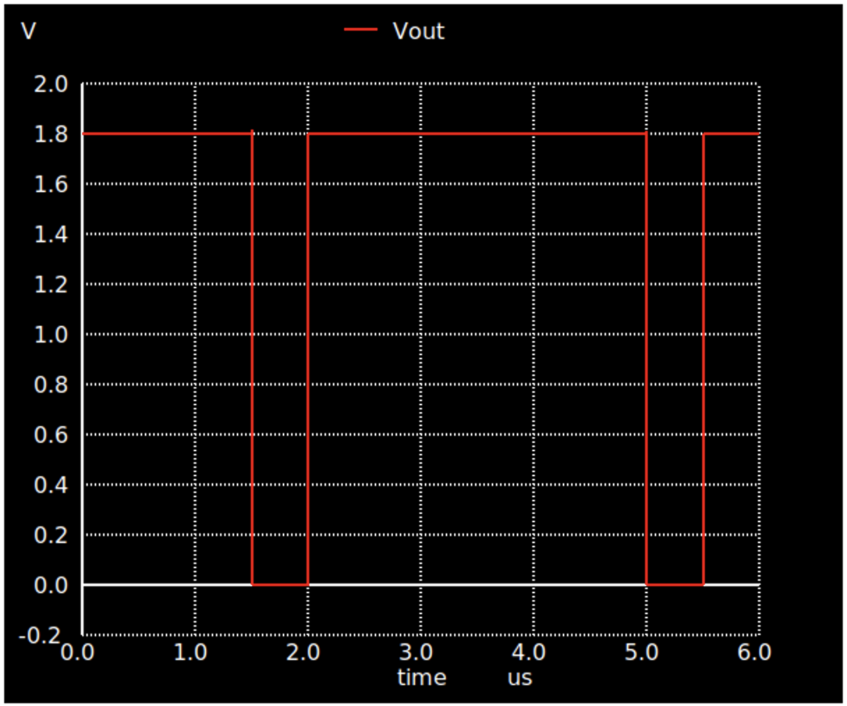
From Fig. 4, we can tell that nand2 output logic 0 only when both Vin1 and Vin2 are at logic 1, which matches with the nand2 function.
References and materials
[1] Basic RLC simulation in Xschem